
Technology
Consideration for depth of field in machine vision
Applicable products
-
CoaXPress 2.0 Camera
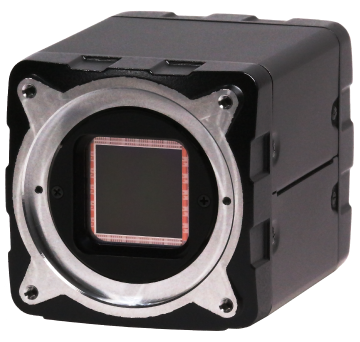
-
USB3 Camera
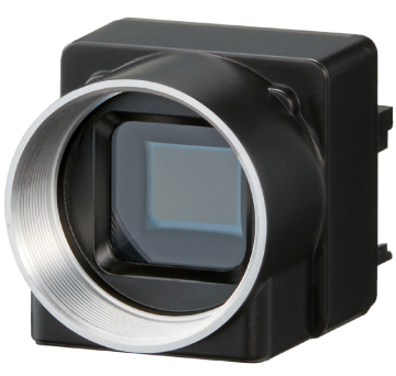
-
GigE Camera
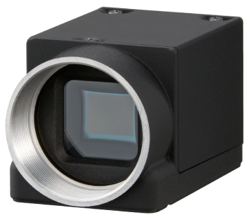
-
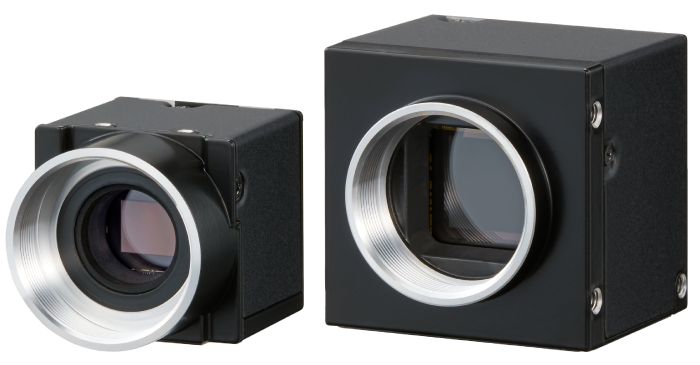
Camera Link Camera
Introduction
In machine vision, opportunity of shooting enlarged subject is supposed to be more than that of general photo shooting. Depth of field is one of popular topics in such usage. This paper describes how to consider the depth of field in machine vision.
1. Imaging and focus
In order to obtain an image using a camera, it is necessary to focus the light from the object as an image on the image sensor using the lens to form an image.
1.1. Imaging of point and F number
The basic performance of imaging with a lens is that "points are imaged as points". As you know, a point is "only a position, not a length or area". If a light source regarded as a point is imaged with "ideal lens", the point in the output image from the sensor will actually have only one pixel, which is an extremely narrow range in actual. Stellar such as Sirius are often compared as point light sources. On the other hand, the sun is hardly regarded as point light source because it is comparatively close to the earth and looks to have area. "Ideal lens" should have characteristics as below.1
- When subject is straight line, its image is also straight line.
- When subject is plane, its image is also plane.
- Image on the plane perpendicular to the optical axis is perpendicular to the optical axis
- Figures in a plane perpendicular to the optical axis and their images are similar to each other. However,
objects on a plane that is not perpendicular to the optical axis and their images are not necessarily similar.
Above characteristics are hardly observed with actual lens due to its optical error. This discrepancy is called aberration. Now let us see the image of point light source by ideal lens. Point image by ideal lens with each F number is shown as "point spread function" here.
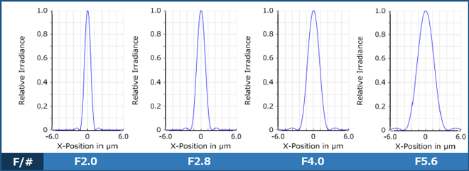
In this chart, horizontal axis represents image height, and ±6.0 μm around the optical axis (optical height=0) is shown (1.2 μm/DIV). And representing strength, vertical axis has maximum value of 1.0 for evaluation at optimal position.
According to this, it is observed that even through ideal lens, point light source with no area or length images in about 2.7 μm diameter with F2, 3.8 μm with F2.8, 5.4 μm with F4.0 and spread to 7.5 μm with F5.6. This spread is caused by wave dynamics of light so called diffraction and indicating size limit of point image squeezed by F number of the lens. This is the phenomena so called small aperture blur, and used as an indication to extract ability of high definition image sensor.
1.2. Focus
PSF described in preceding paragraph is in the position of best point image. However, what will happen if the imaging plane moves back and forth (defocus)? Defocus with F2.0 is shown here. (Because of ideal lens, PSF in positive/negative direction are same. )
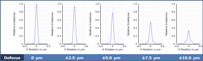
As shown in these charts, the further the imaging plane position moves away from the best position, the weaker strength become and the wider the size of point image become. In other words, contrast decreases. "Defocus" means out of focus, spread point image and decreased strength. However, degree of blur cannot be defined generally because its standard depends on purpose of camera use and image processing method. In next paragraph, we will consider "depth of field" as the theme of this material including standard of blur.
2. What is depth of field?
2.1. Depth of field
Generally, depth of field is explained for photo shooting. However, in our technical material2, it is explained as follows together with "depth of focus".
- Shooting lens works to make image of the subject. At this time, a point has to be imaged as a point. It can be intuitively imagined that there is only one focus point and blur grows as it moves away from the focus point. In depth direction along the optical axis of actual camera system, the focus range is not one point but there is a certain width that can be considered as in focus. This is called "depth of focus".
- "Depth of focus" is a description about near the image sensor inside the camera. On the other hand, there is a certain width that can be considered as in focus at subject side also. This is called "depth of field".
2.2. Depth of field and permissible circle of confusion
"Permissible circle of confusion" is used as variable to calculate "depth of field". "Circle of confusion" herein means a circular image of a point formed by a lens. The smallest size that cannot be recognized as blur is especially called the "permissible circle of confusion diameter".
In the photographic industry, even today, when digital cameras are the mainstream, the permissible circle of confusion values similar to silver halide films, assumed to be "printed on photographic paper of a certain size and viewed visually at a certain distance, are commonly used3. In the machine vision however, since image processing is performed with the data of each pixel, visual observations cannot be used as a reference as in photographs. "Permissible circle of confusion diameter" is determined by "pixel pitch" of the sensor or optical imaging limit of the lens which is called "airy disk diameter". The larger of the "pixel pitch" or "airy disk diameter" is "permissible circle of confusion diameter"4. "Depth of field" calculated in such way means depth which the sensor cannot recognize as blur. This result is the range to indicate the hardest (shallow and narrow) condition. Even the value is out of this range, it does not necessarily means too blur to detect characteristics of the subject.
4 JIIA Lens Working Group. (2010). JIIA LER-006-2010: Parameters for a Depth of Focus. Japan Industrial Imaging Association.
3. Consideration for depth of field in machine vision
3.1. Contrast and resolution
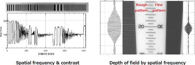
Requirements for machine vision images include "contrast" and "resolution (resolution capability)". "Contrast" means the difference in brightness between a bright part (white) and a dark part (black) in an image. The higher the contrast, the easier it is to determine the characteristics of the subject. The "resolution" is the closest limit at which two slightly separated points can be seen separately. However, as a guideline of separation, it is necessary to have about 10% contrast (MTF) in the camera output image.5
3.2. Spatial frequency and depth of field
The period per unit length of the black and white stripes is called the spatial frequency, and it is indicated as unit of "lines/mm" or "lp/mm". As for the optical characteristics of machine vision systems, the higher the spatial frequency (the larger the value), the lower the contrast. And, the finer the stripes, the smaller the difference in brightness, and the easier to feel blurred focus. This means that the coarser the stripe, the less the effect of blurring, and the easier to recognize the pattern. In machine vision, the value resulted by "pixel pitch" and "airy disc diameter" described above is the shallowest depth of field. However, for most applications in machine vision, spatial frequencies lower than the pixel pitch are used for image processing, and in fact, a deeper depth of field can be obtained than calculated value using the "permissible circle of confusion diameter".
[Reference] PSF variation by F number / Defocus
Variation of F number in ideal lens and point spread function (PSF) by defocus.
![[Reference] PSF variation by F number / Defocus](../../../images/technology-en/t0008/t_t0008_04.png)