
Technology
Overlapped Trigger function
Applicable products
-
CoaXPress 2.0 Camera
-
USB3 Camera
-
GigE Camera
-
Camera Link Camera
Introduction
There is a strong market requirement for minimizing the interval between trigger inputs in Trigger mode. To satisfy this requirement, some of Teli’s camera models are equipped with an overlapped trigger function.
1.What is an overlapped trigger function?
A camera’s operation in Trigger mode proceeds in the following sequence:
(1) Trigger input
(2) Exposure
(3) Sensor output
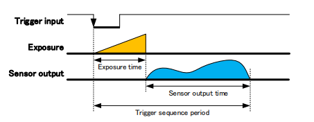
When the overlapped trigger function is not used, the interval between consecutive trigger inputs must be greater than the above sequence period.
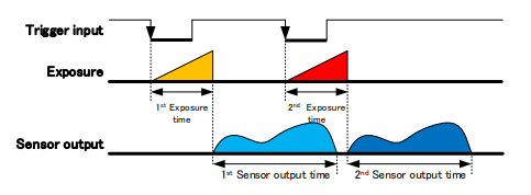
However, the overlapped trigger function makes it possible to apply the next trigger signal prior to the completion of Step 3, “Sensor output.”
2.Models equipped with an overlapped trigger function
As of September 2021, the following models provide an overlapped trigger function.
- EX series (CMOS, High performance) - EX670AMG-X
- DDU series (CMOS, High performance) - DDU1607MG / DDU1607MCG / DDU1607MCF / DDU1207MG / DDU1207MCG / DDU1207MCF
- DU series (CMOS, High performance) - DU1207MG / DU1207MCG / DU1207MCF / DU657M / DU657MC
- BU series (CMOS, Compact) - BU2409MG / BU2409MCG / BU2409MCF / BU1207MG / BU1207MCG / BU1207MCF / BU505MG / BU505MCG / BU505MCF / BU406M / BU406MN / BU406MC / BU406MCF / BU302MG / BU302MCG / BU302MCF / BU238M / BU238MC / BU238MCF / BU205M / BU160MG / BU160MCG / BU160MCF / BU040MG / BU040MCG / BU040MCF
- BU series (CCD, Compact) - BU030 / BU030C / BU030CF / BU031 / BU130
- BG series (CMOS) - BG505LMG / BG505LMCG / BG505LMCF / BG302LMG / BG302LMCG / BG302LMCF / BG205M-CS / BG160M / BG160MCG / BG160MCF / BG040M / BG040MCG / BG040MCF
- BG series (CCD) - BG030 / BG030C / BG030CF / BG031 / BG080 / BG130 / BG202 / BG202C / BG202CF
- BC series (CMOS) - BC505LMG / BC505LMCG / BC505LMCF / BC302LMG / BC160M / BC040M
- CSC series (CMOS) - CSC6M100BMP11 / CSC6M100CMP11
3.Enabling the overlapped trigger function
No camera settings are necessary to use the overlapped trigger function. This function is automatically enabled when trigger inputs are applied with a certain interval.
4.Restrictions on the overlapped trigger function
The overlapped trigger function has the following restrictions:
4.1.Restriction on the minimum trigger interval
In order for an image sensor to work properly, the overlapped trigger operation must finish the sensor output prior to the completion of an exposure.
Therefore, the minimum trigger interval in Overlapped Trigger mode is as follows:
a) When the exposure initiated by the next trigger input is shorter than the sensor output period
When the exposure initiated by the next trigger is shorter than the sensor output period, the following equation is true:
minimum_trigger_interval = exposure_time_initiated_by_previous_trigger + sensor_output_period – exposure_time_initiated_by_next_trigger
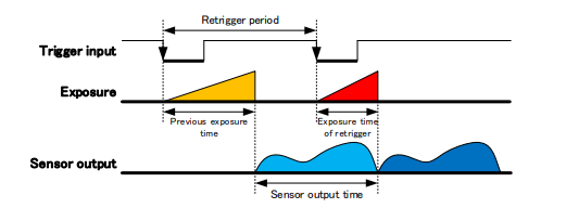
(when the sensor output period is longer than the exposure time)
When the exposure time is fixed, the minimum trigger interval becomes as follows if the periods of exposures initiated by the previous and next trigger inputs are equal:
minimum_trigger_interval = sensor_output_period
(when the exposure time is fixed)
b) When the period of an exposure initiated by the next trigger input is longer than the sensor output period
When the period of an exposure initiated by the next trigger input is longer than the sensor output period, the video output produced by the previous trigger finishes during the exposure initiated by the next trigger.
In this case, the next trigger input can be applied immediately after the exposure initiated by the previous trigger ends. Therefore, the minimum trigger input is:
minimum_trigger_input = expsoure_time_initiated_by_previous_trigger_input
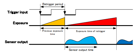
(when the exposure time is longer than the sensor output period)
c) When trigger inputs are applied at an interval shorter than the minimum trigger interval
In the case of TriggerSequence0 (Edge mode) or Fix mode, the next trigger input becomes invalid if it is applied before the minimum trigger interval elapses after the previous trigger input. If the Event function is enabled, a FrameTriggerError event is issued.
In the case of TriggerSequence1 (Level mode) or Pulse width mode, a camera cannot calculate the minimum trigger interval because it cannot obtain the exposure time beforehand. Therefore, the next trigger input becomes valid, but the exposure time is extended till the end of the sensor output period.
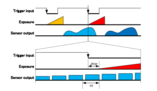
4.2.Jitter occurring between the next trigger input and the start of exposure
Typical image sensors produce noise in the video output if an exposure is initiated during the sensor output period. To prevent this noise, the Overlapped Trigger mode initiates an exposure during the horizontal blanking interval (i.e., an unused gap between the end of one line and the beginning of the next line).
Therefore, jitter occurs in Overlapped Trigger mode. The maximum jitter is equal to the horizontal period from the trigger input to the beginning of an exposure.
The horizontal period is specified in the specifications and user instruction manuals for the BC and some other series.
The horizontal period of other models can be approximated as follows:
Horizontal period = 1,000,000 / AcquisitionFrameRate / Height [us]
Appendix - Using the trigger delay function to reduce jitter at the beginning of an exposure
Some models provide the trigger delay function for reducing the jitter that occurs at the beginning of an exposure discussed in Section 4.2.
Jitter can be reduced by setting the trigger delay to a value greater than the horizontal period.
The following models support the jitter reduction function.
- DDU series (CMOS, High performance) - DDU1207MG / DDU1207MCG / DDU1207MCF
- DU series (CMOS, High performance) - DU1207MG / DU1207MCG / DU1207MCF
- BU series (CMOS, Compact) - BU2409MG / BU2409MCG / BU2409MCF / BU1207MG / BU1207MCG / BU1207MCF / BU505MG / BU505MCG / BU505MCF / BU302MG / BU302MCG / BU302MCF / BU238M / BU238MC / BU238MCF / BU160MG / BU160MCG / BU160MCF / BU040MG / BU040MCG / BU040MCF
- BU series (CCD, Compact) - BU030 / BU030C / BU030CF / BU031 / BU130
- BG series (CMOS) - BG505LMG / BG505LMCG / BG505LMCF / BG302LMG / BG302LMCG / BG302LMCF / BG160M / BG160MCG / BG160MCF / BG040M / BG040MCG / BG040MCF
- BC series (CMOS) - BC505LMG / BC505LMCG / BC505LMCF / BC302LMG / BC160M / BC040M