
Technology
Strobe control from a camera
Applicable products
-
CoaXPress 2.0 Camera
-
USB3 Camera
-
GigE Camera
-
Camera Link Camera
Introduction
The BU and BG series, the BC series models with an I/O connector, and the DU, DDU, and EX series (hereinafter collectively referred to as the B/D/E series) provide a high-performance general-purpose input/output (GPIO).
Combining the functions of the GPIO makes it possible to control the strobe light timing from a camera.
1.GPIO overview
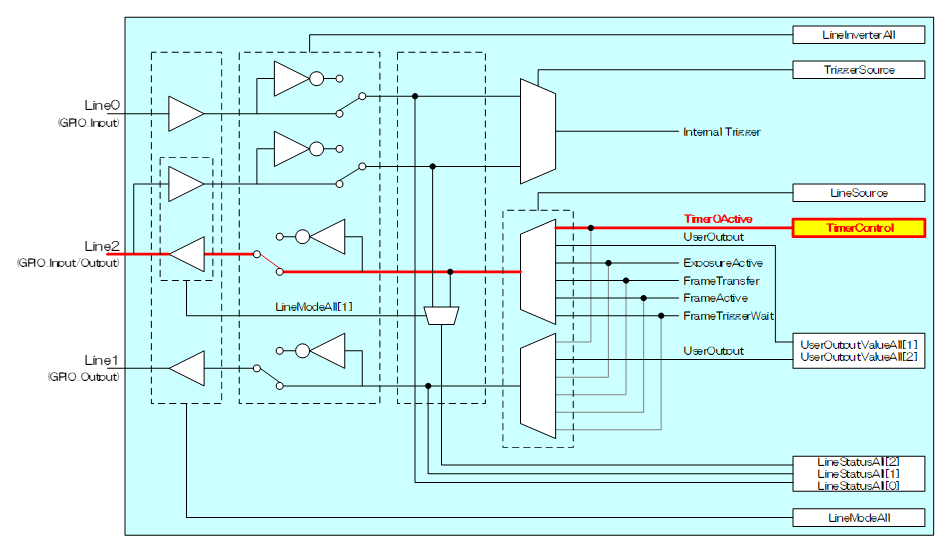
As an example, the following shows the configuration of the GPIO of the BU series:
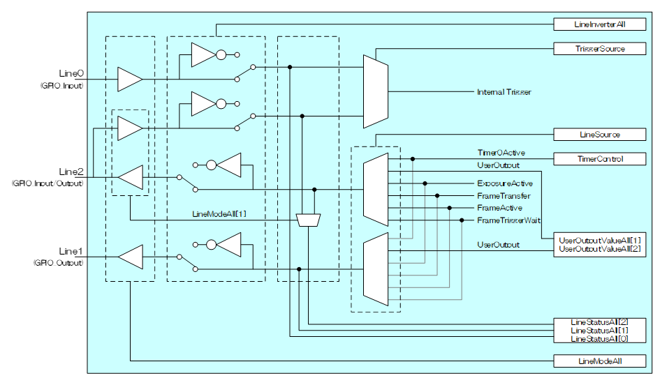
Either an output pin (Line1 in the case of the BU series) or an I/O pin (Line2 in the case of the BU series) can be used for strobe control. To use an I/O pin, it is necessary to set the relevant bit of LineModeAll to the output mode.
// Setting Line2 to the output mode
SetCamLineMode(s_hCam, CAM_LINE_SELECTOR_LINE2, CAM_LINE_MODE_OUTPUT );
2.GPIO polarity
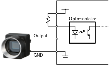
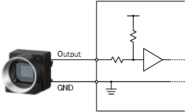
The input polarity depends on the strobe connected.
In the case of the B/D/E series, the factory default of the GPIO output polarity is negative. To use a strobe with an input pulse of positive polarity, the LineInverterAll register should be programmed to reverse the camera’s polarity.
The following shows an example of a strobe connection.
// Inverting the output signal of Line2 to set the polarity to positive
SetCamLineInverter(s_hCam, CAM_LINE_SELECTOR_LINE2, true );
3.Methods of setting the strobe output signal
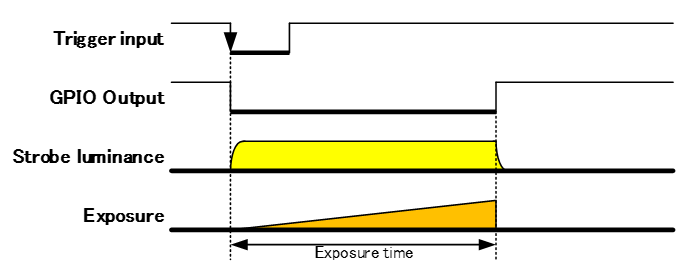
3.1.Using ExposureActive
When a camera and a strobe are connected in a typical manner, this method is used to fire the strobe during the camera's exposure.
Use this method for TriggerMode = Off, TriggerSequence1 (Level mode) and TriggerSequence6 (Bulk mode).
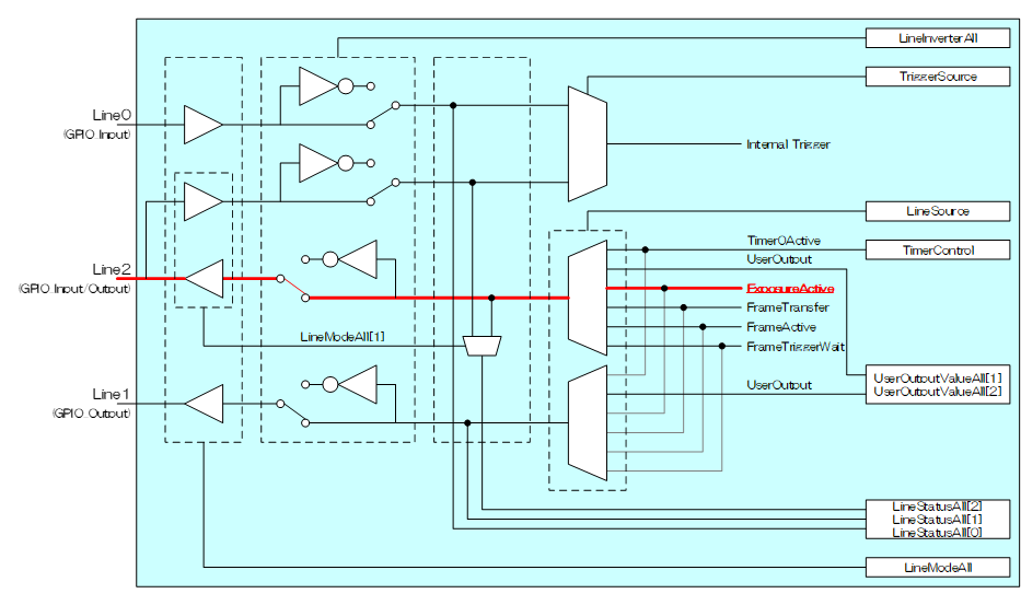
// Configuring the output signal of Line2 for ExposureActive
SetCamLineSource (s_hCam, CAM_LINE_SELECTOR_LINE2, CAM_LINE_SOURCE_EXPOSURE_ACTIVE);
3.2.Using Timer0Active
In some cases, the strobe flash and discharge delays can be an issue when the exposure time is short. In such cases, it is effective to set the expose time to a period during which the strobe brightness level is stable.
The B/D/E series provides a Pulse generator called TimerControl. This function makes it possible to set strobe flash and camera exposure parameters arbitrarily.
This method is available only TriggerSequence0 (Edge mode).
*BG Series (CCD) and BG205M-CS don’t have this function.
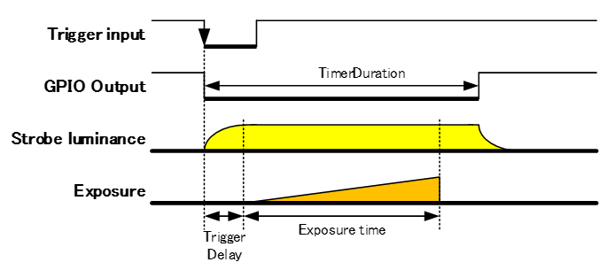
// Example of setting an exposure of 500 μs at the center of the strobe flash time of 700 μs
// Configuring the reference signal for the Timer0Active signal to accept a trigger
SetCamTimerTriggerSource(s_hCam, CAM_TIMER_TRIGGER_SOURCE_FRAME_TRIGGER );
// Setting a delay of the Timer0Active signal (zero delay)
SetCamTimerDelay( s_hCam, 0 );
// Setting the width of the Timer0Active signal to 700 μs
SetCamTimerDuration( s_hCam, 700 );
// Configuring the output signal of Line2 for Timer0Active
SetCamLineSource (s_hCam, CAM_LINE_SELECTOR_LINE2, CAM_LINE_SOURCE_TIMER0_ACTIIVE );
// Setting the latency between the detection of a trigger signal and the beginning of exposure to 100 μs
SetCamTriggerDelay( s_hCam,100 );
// Setting the exposure time to 500 μs
SetCamExposureTime( s_hCam, 500 );